Anycast DNS Using RIP (continued)

The third article in the Anycast DNS series continues our discussion of implementing Anycast DNS using RIPv2
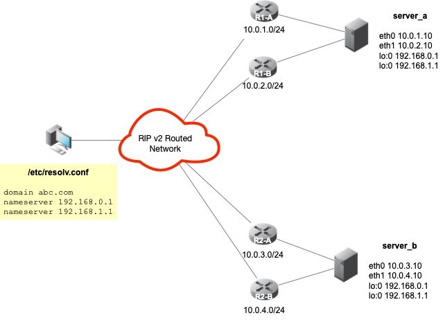
This article is a continuation of Anycast DNS using RIP in our series on Anycast DNS. In this next recipe, two Anycast VIPs will be advertised on two (2) DNS servers that are multi-homed on different subnets by different routers using RIP v2. In this recipe, we'll review the commands that will be needed to add the additional interfaces to our Quagga configuration, as well as, briefly discuss how to handle multiple default gateways on multi-homed hosts. The figure below depicts our configuration for this recipe:
Multi-homed Hosts and Multiple Gateways
Now that our servers are configured with two (2) physical network interfaces on two (2) different segments, each with a different upstream router, we must configure our servers with multiple default gateways to accommodate the increased redundancy. In this recipe, we use ICMP Router Discovery Protocol (IRDP) on both the routers and servers to assist in default gateway discovery and configuration, as well as, dead gateway detection or "blackhole detection". IRDP is supported by Cisco, Sun Microsystems, and Linux. For more information on IRDP, consult RFC 1526 - ICMP Router Discovery Messages. On the Sun platform, IRDP is implemented as a daemon called in.rdisc. This same software was ported to the Linux platform and is now included in the Iputils RPM, called rdisc.
IRDP Client-side Configuration
On our Anycast DNS servers, all that is required is to have rdisc start at boot time with the -a option. The -a option will force the "client" to accept all routers independently of the preference they have in their announcement messages. Normally, rdisc will accept only messages from the router or routers with the highest preference.
IRDP Server-side Configuration
Configure both of the upstream Cisco routers to act as the IRDP "server" as follows:
R1-A# configure terminal
R1-A(config)# interface vlan_server_a
R1-A(config-if)# ip idrp
R1-A(config-if)# ip idrp multicast
This is the minimum configuration required to setup IRDP on the Cisco. Other values can be set to further "tweak" the configuration.
Once the configuration is established on both the "client" and "server", reboot the Anycast DNS Server. Once the server comes up, it should automatically "learn" and configure itself with both upstream routers as default gateways. Should one of the upstream routers be taken down for maintenance or crash, the routes will be removed, and both of our Anycast VIPs will still be reachable via the other interface's default gateway. This adds a significant level of resiliency to our overall configuration.
Step 1 - Adding The Second Anycast VIP
On server A, assuming we already have lo0, we add our second Anycast VIP as follows:
ifconfig lo:1 192.168.1.1 netmask 255.255.255.255
Ensure this second loopback device is properly configured in the /etc/sysconfig/network-scripts directory so that it will be active at boot time.
Step 2 - Add Anycast VIP to Zebra (Quagga)
This can be done interactively by issuing the command telnet localhost 2601 and supplying the necessary credentials to get to the enable prompt.
server_a# configure terminal
server_a(config)# interface lo:1
server_a(config-if)# ip address 192.168.1.1/32
server_a(config-if)# ipv6 nd supress-ra
server_a(config-if)# exit
server_a(config)# exit
Once again, this assumes we already have zebra configured with the first Anycast DNS address of 192.168.0.1/32. Save the configuration when done to the /etc/quagga/zebra.conf using the write file command.
Step 3 - Add Anycast VIP to ripd (Quagga)
This can be done interactively by issuing the command telnet localhost 2602.
server_a# configure terminal
server_a(config)# router rip
server_a(config-router)# network 192.168.1.0/24
server_a(config-router)# network lo:1
server_a(config-router)# exit
server_a(config)# exit
It is assumed that the Anycast VIP of 192.168.0.1 is already configured and we're simply adding the second VIP to the configuration. Save the configuration when done to the /etc/quagga/ripd.conf using the write file command.
Step 4 - Add Anycast VIP to both upstream routers R1-A and R1-B
R1-A# configure terminal
R1-A(config)# router rip
R1-A(config-router)# network 10.0.0.0
R1-A(config-router)# network 192.168.0.0
R1-A(config-router)# network 192.168.1.0
R1-A(config-router)# exit
R1-A(config)# exit
Save the configuration when done using the write memory command. Repeat the same command for the other upstream router R1-B.
R1-B# configure terminal
R1-B(config)# router rip
R1-B(config-router)# network 10.0.0.0
R1-B(config-router)# network 192.168.0.0
R1-B(config-router)# network 192.168.1.0
R1-B(config-router)# no auto-summary
R1-B(config-router)# exit
R1-B(config)# exit
Step 5 - Repeat steps 1-4 on Server B and its upstream routers
Optional configuration steps
Adding Outbound IP Access Control List
One of the additional steps that can be taken is to add an IP access list to our Quagga configurations to prevent any unwanted routes from being defined and/or leaking out. This can be done in one of two ways, you can make this change by editing the /etc/quagga/ripd.conf file directly or you can use the vty interface. We'll show how to do this using the interactive vty session:
server_a# configure terminal
server_a(config)# router rip
server_a(config-router)# distribute-list anycast out eth0
server_a(config-router)# distribute-list anycast out eth1
server_a(config-router)# exit
server_a(config)# access-list anycast permit 192.168.0.1/32
server_a(config)# access-list anycast permit 192.168.1.1/32
server_a(config)# access-list anycast deny any
server_a(config)# exit
The last command will flush all our previous commands to disk file, and the /etc/quagga/ripd.conf file will be updated with our new IP ACL. Now, only the two Anycast VIPs will be allowed to be propagated to our upstream routers.
Adding Inbound IP Access Control List
We can take the whole IP access list thing a step further. We can tell the Cisco to ONLY accept Anycast VIP routes from a particular interface. This is done by applying an inbound IP access list to each upstream Cisco router shown with the following commands:
R1-A# configure terminal
R1-A(config)# access-list 10 permit 192.168.0.1
R1-A(config)# access-list 10 permit 192.168.1.1
R1-A(config)# access-list deny any
R1-A(config)# router rip
R1-A(config-router)# distribute-list 10 in vlan_server_a
R1-A(config-router)# end
As you can see, the vty command syntax of Quagga and Cisco are almost identical. It makes configuring Anycast a snap when using these two products together. So, now our Cisco will only accept our two Anycast VIPs 192.168.0.1/32 and 192.168.1.1/32 by way of the vlan_server_a VLAN interface.
Adding RIP v2 Authentication
For added security, we can use RIP v2 Authentication. RIP v2 allows packets to be authenticated via either an insecure plain text password, included with the packet, or via a more secure MD5 based HMAC (keyed-Hashing for Message AuthentiCation). Using RIP v2 Authentication prevents routing updates from unauthenticated sources, while allowing normal route queries to take place. To enable RIP v2 Authentication, we must configure it on both our server and router in the following manner:
Server A is configured by using
server_a# configure terminal
server_a(config)# key chain anycast
server_a(config)# key 1
server_a(config)# key-string Passw0rd!
server_a(config)# interface eth0
server_a(config-if)# ip rip authentication mode md5
server_a(config-if)# ip rip authentication key-chain anycast
server_a(config-if)# exit
server_a(config)# exit
And on the Cisco router R1:
R1-A# configure terminal
R1-A(config)# key chain anycast
R1-A(config)# key 1
R1-A(config)# key-string Passw0rd!
R1-A(config)# interface vlan_server_a
R1-A(config-if)# ip rip authentication mode md5
R1-A(config-if)# ip rip authentication key-chain anycast
R1-A(config-if)# exit
R1-A(config)# exit
Now, Server A and router R1-A will use RIP v2 Authentication before exchanging their routing updates. The same configuration would need to be applied to R1-B, R2-A, and R2-B.
Passive Interfaces
RIP v2 can use either multicast or unicast packets to exchange routing information. Normally, RIP v2 uses IP multicast as its means for sharing routing information and performing routing updates. We can refine our configuration on the server-side by placing the interface into passive mode. Passive mode is used when either the neighbors don't understand multicast, or to purposefully squelch the multicast traffic in favor of unicasting. To use passive interfaces, you must tell the server what it's neighbor or upstream router is. We recommend the use of passive interfaces on the server side and this can be done as follows:
server_a# configure terminal
server_a(config)# router rip
server_a(config-router)# neighbor 10.0.1.1
server_a(config-router)# passive-interface default
server_a(config-router)# exit
server_a(config)# exit
The network interface on server A is now configured to operate in passive mode, and we've explicitly configured its upstream neighboring router interface. Serer A will exchange RIP v2 routing updates and information with R1-A using unicasting instead of multicasting.
These are just a few extra configuration tips that can be used to further optimize the Anycast DNS recipes when using RIP v2.
Series
DNS Anycast using static routes
DNS Anycast using RIP
DNS Anycast using RIP (cont)
DNS Anycast using OSPF (basic)
DNS Anycast using OSPF (advanced)
DNS Anycast using BGP